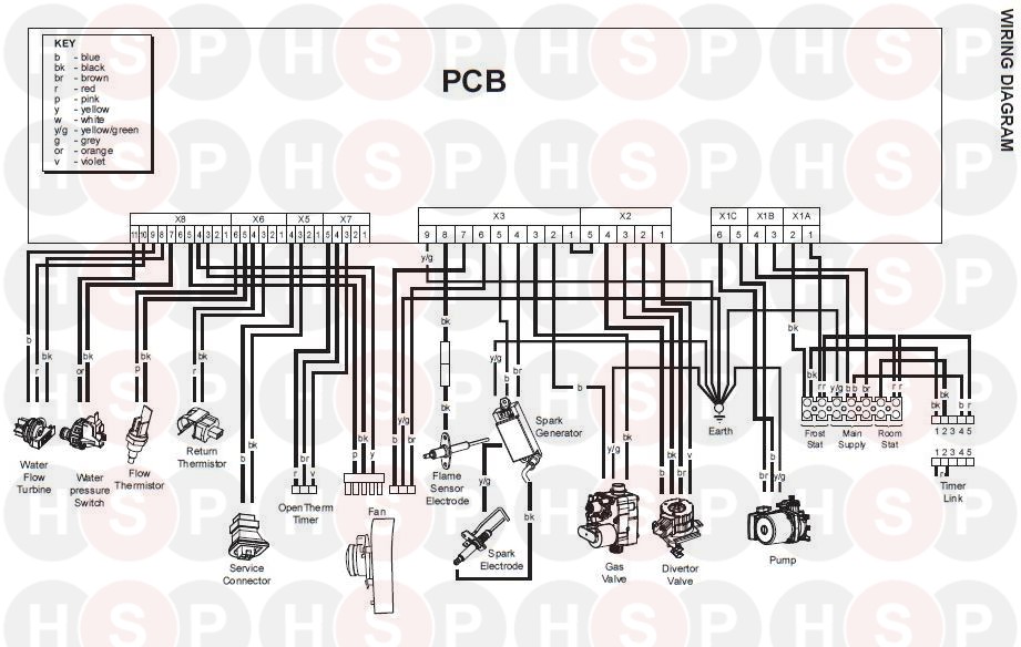
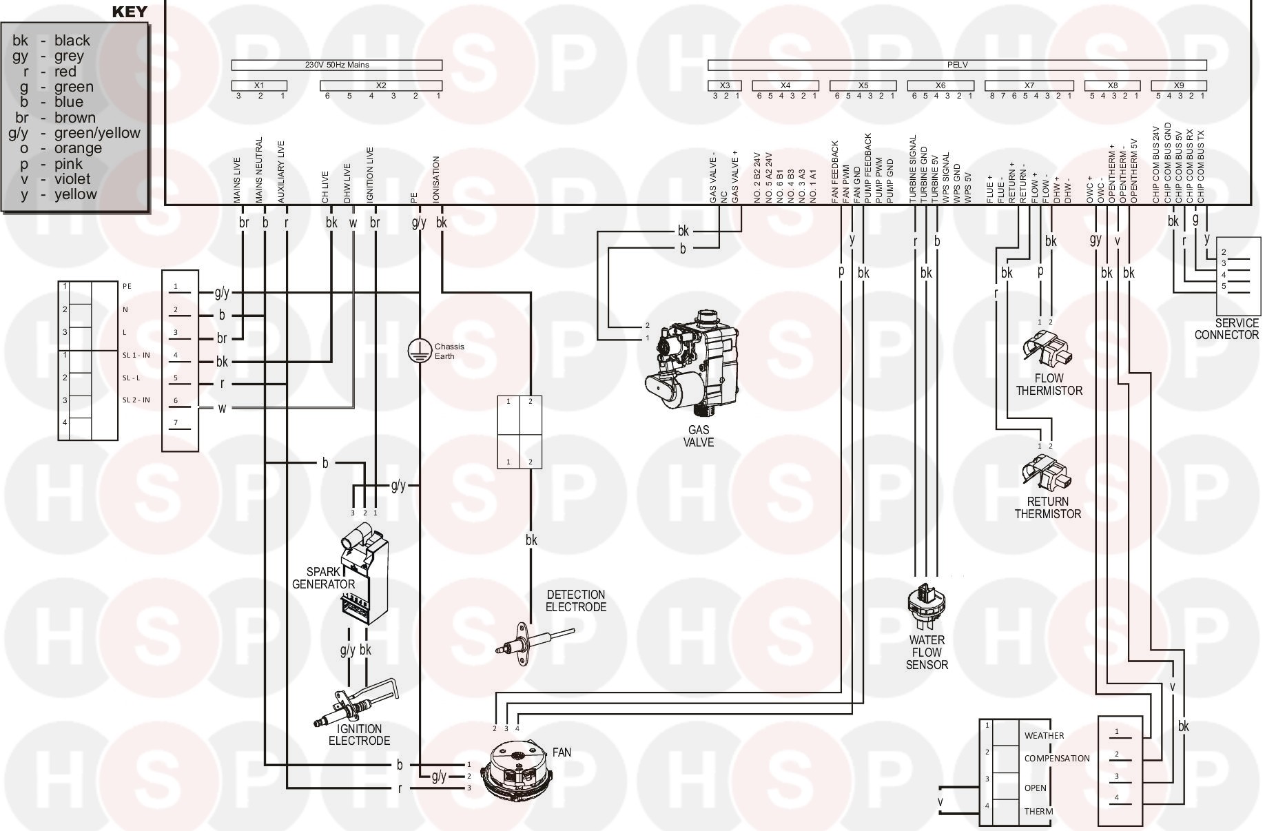
Ideal Combi Boiler Wiring Diagram
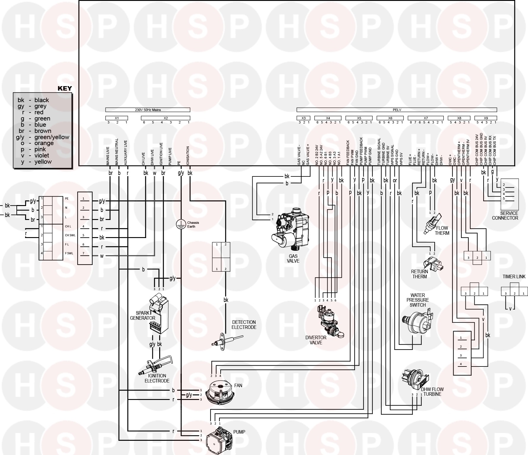
Ideal Logic Combi 24 Wiring Diagram Diagram Heating Spare Parts
Ideal Instinct Combi 30 Wiring Diagram Diagram Heating Spare Parts
Ideal Independent Combi 30 Wiring Diagram Diagram Heating Spare Parts
Ideal Logic Combi 35 Wiring Diagram Abk Onwards Diagram Heating Spare Parts
Ideal Logic Combi C30ie Wiring Diagram Heating Spare Parts
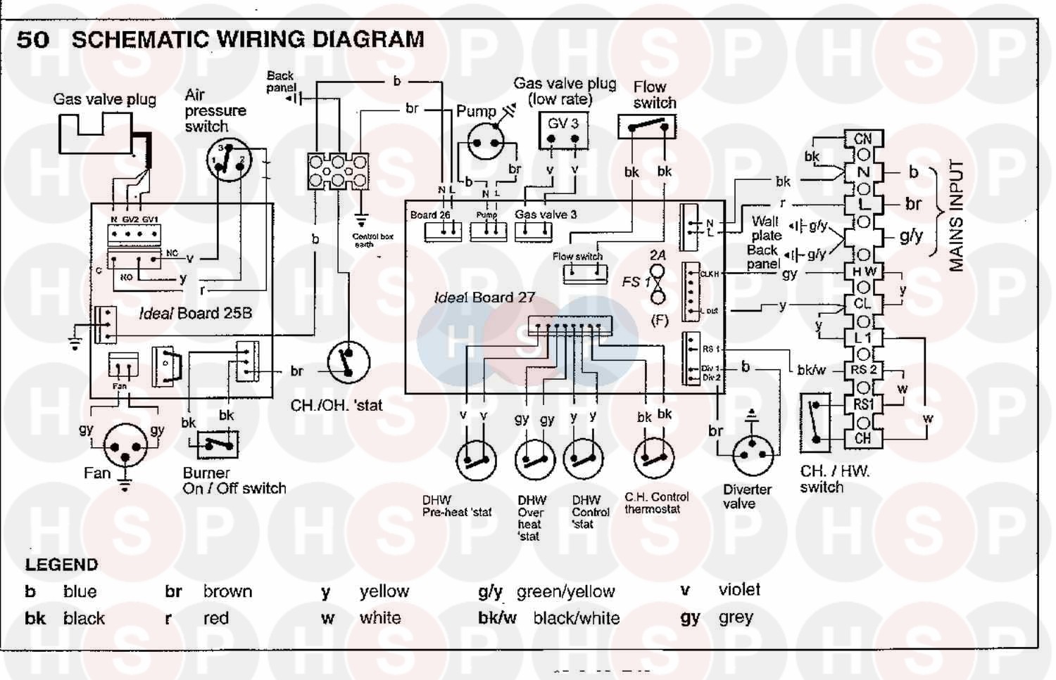
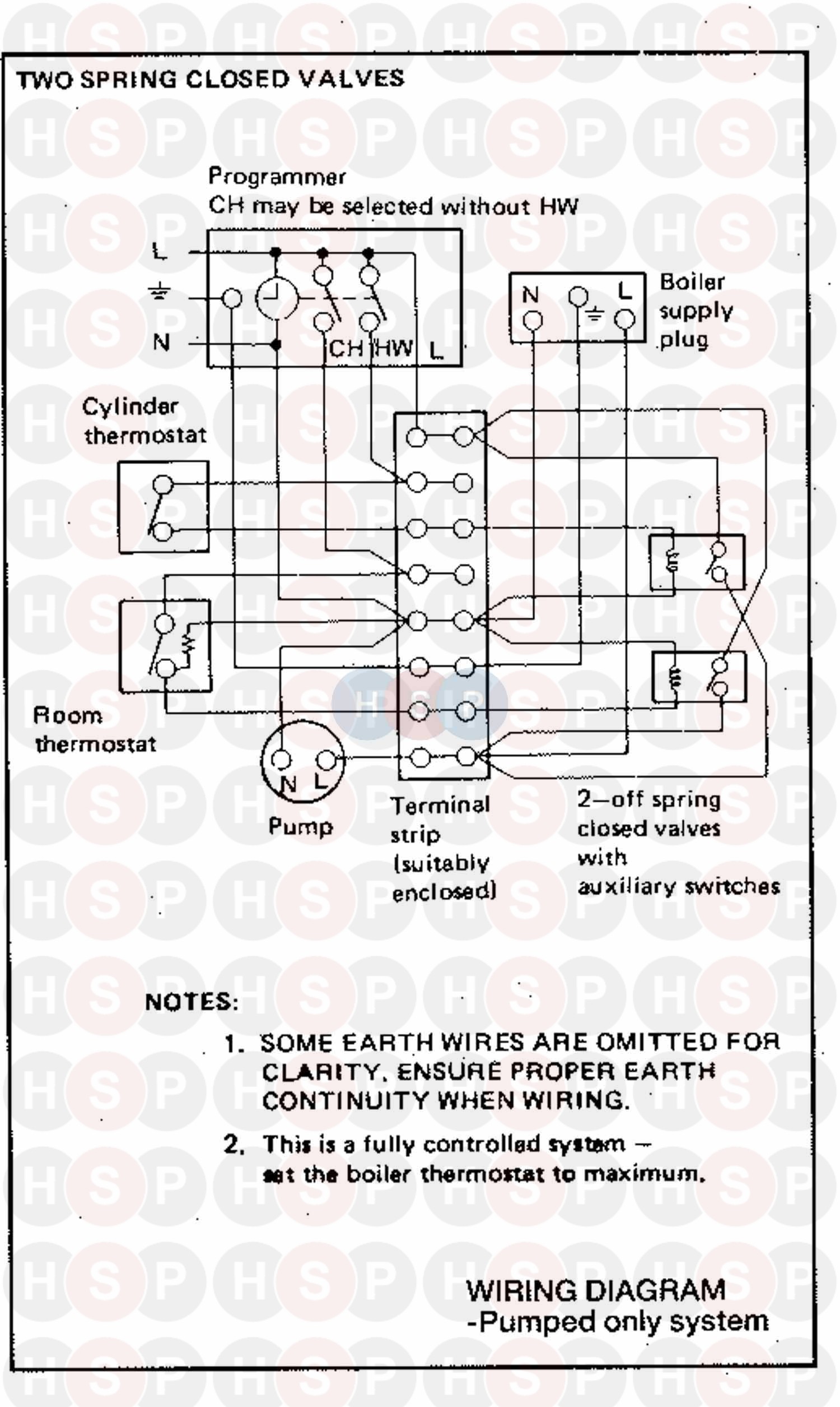
Ideal Classic Rs 40 Wiring Diagram 4 Diagram Heating Spare Parts
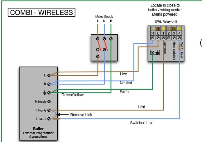
Attached is the wiring diagram for the receiver.
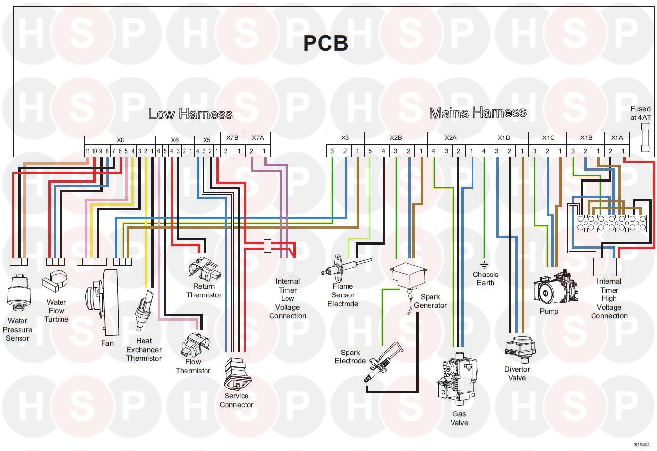
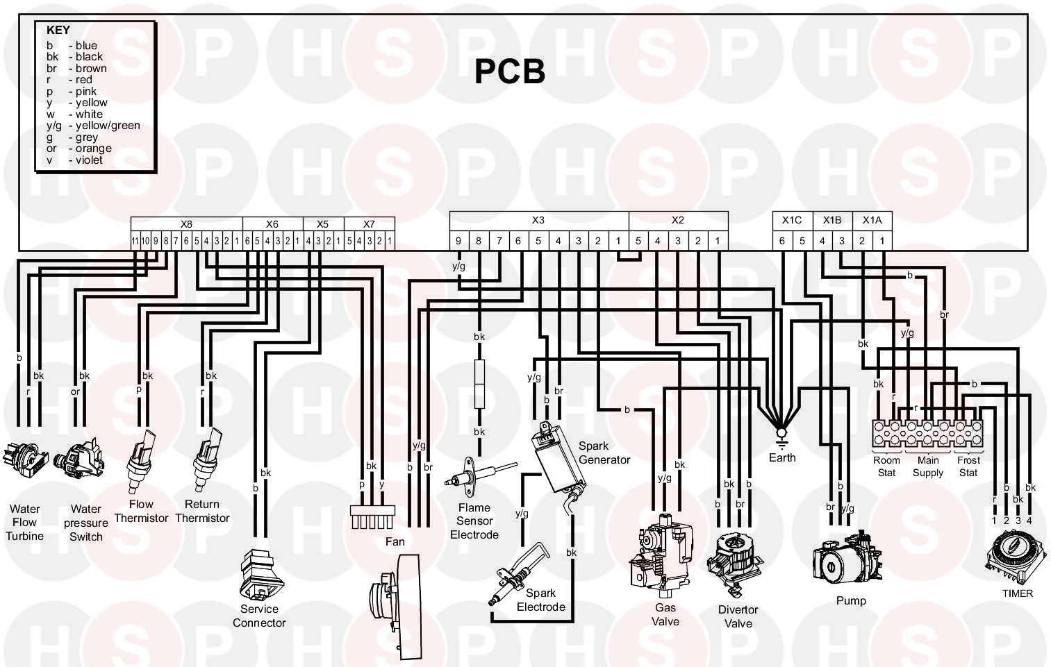
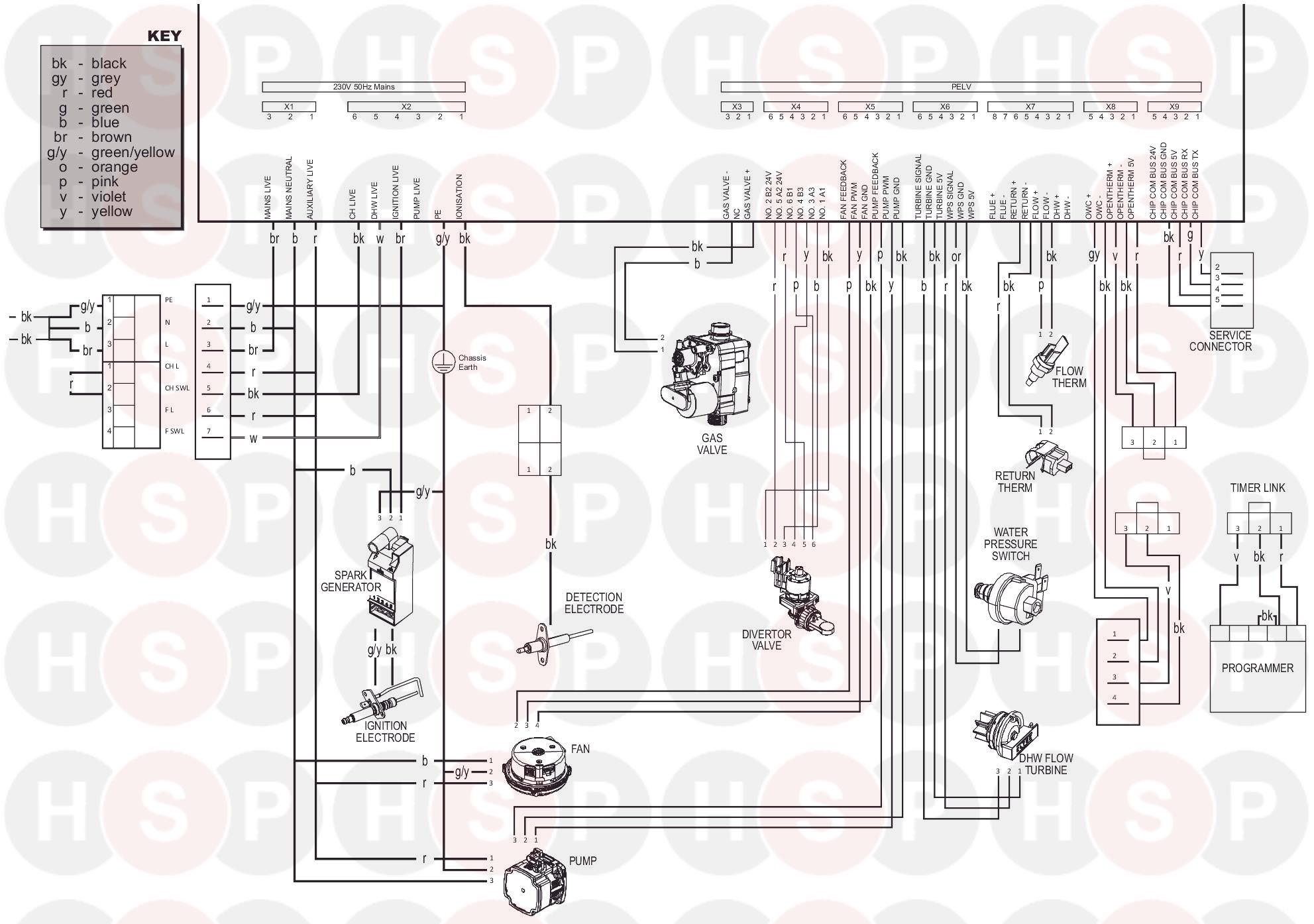
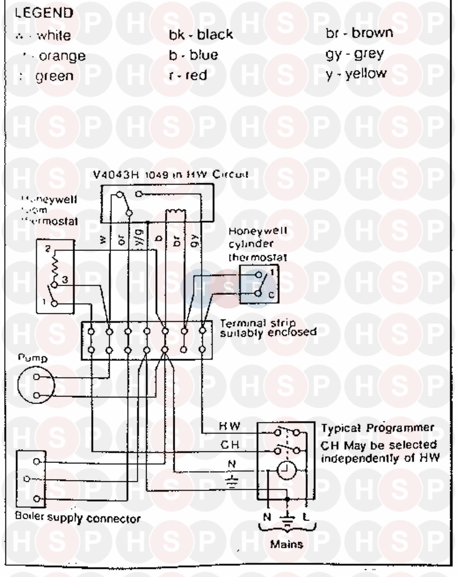
Ideal combi boiler wiring diagram. Many combination boilers have an integral timer or programmer. I believe it is now wired up correctly as the heating is coming on and off when i have it on manual and raise the room temp. Here is a picture of. Logic combi 24 boiler pdf manual download.
As you can see it only has 5 wires earth live neutral t1 t2. Search by boiler type. Condensing boiler n a n a yes yes yes low temperature boiler n a n a no no no b1 boiler n a n a no no no cogeneration space heater n a n a no no no equipped with a supplementary heater n a n a no no no combination heater n a n a yes yes yes nominal heat output for space heating full load p4 kw 24 3 24 3 24 3 part load p1 kw 8 0 8 0 8 0. Ideal logic combi installation and servicing benchmark checklist completed.
Wiring diagram installation 30 wiring diagram ideal logic combi installation and servicing. Here is a picture of the boiler wiring diagram at the moment. Logic combi 35 logic combi 30. Ideal logic combi 24 wiring diagram heating spare parts pump overrun diynot forums abk onwards hive for a 30 heat h 15 salus rf500 wrg 2562 35 esp1 help with and please external programmers combination boilers.
And the hive single channel receiver needs 6 e n l 1 2 3. Greenstar cdi compact wiring diagram internal view gas combi view details greenstar cdi highflow wiring diagram. There are two main types 2 wire and 3 wire. The choice will depend on the boiler.
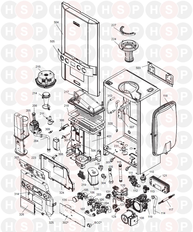
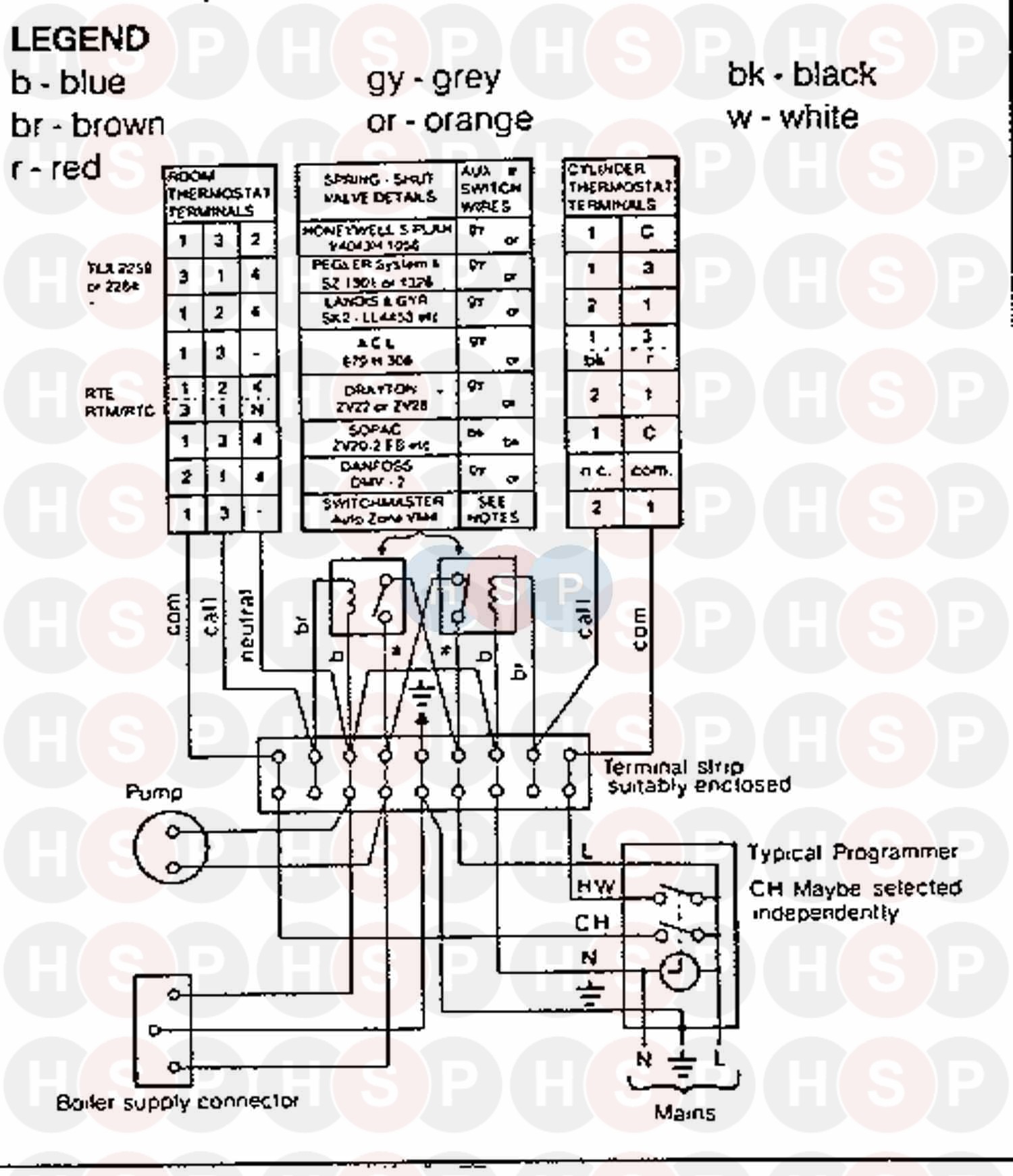
A flow chart to assist is provided on page 65. The circulator pump for the central heating is normally an intergral part of the boiler so no additional wiring is required. Boilers central heating boilers new boilers ideal boilers. Boiler diagrams spare parts and user manuals for ideal logic combi 30 boiler exploded view 24 hour delivery on genuine manufacturer boiler spares 30 day money back guarantee.
Ideal Logic Heat H 18 Wiring Diagram Heating Spare Parts

Nest Heat Link Control Wiring To Ideal Logic Plus 30 Boiler Overclockers Uk Forums
Ideal Logic Pump Overrun Diynot Forums
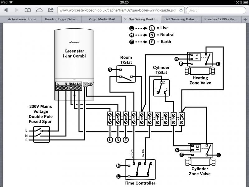
Diagram Crown Boiler Wiring Diagram Full Version Hd Quality Wiring Diagram 1lightbulbwiring1 Lalibrairiedelouviers Fr
Ideal Classic Combi 280 Wiring Diagram 2 Diagram Heating Spare Parts
New Boiler Relay Hive Home Diynot Forums
Ideal Classic Rs 60 Wiring Diagram 3 Diagram Heating Spare Parts
Hive Wiring For A Logic 30 Combi Diynot Forums
Hive To Ideal Logic 24 Combi Diynot Forums
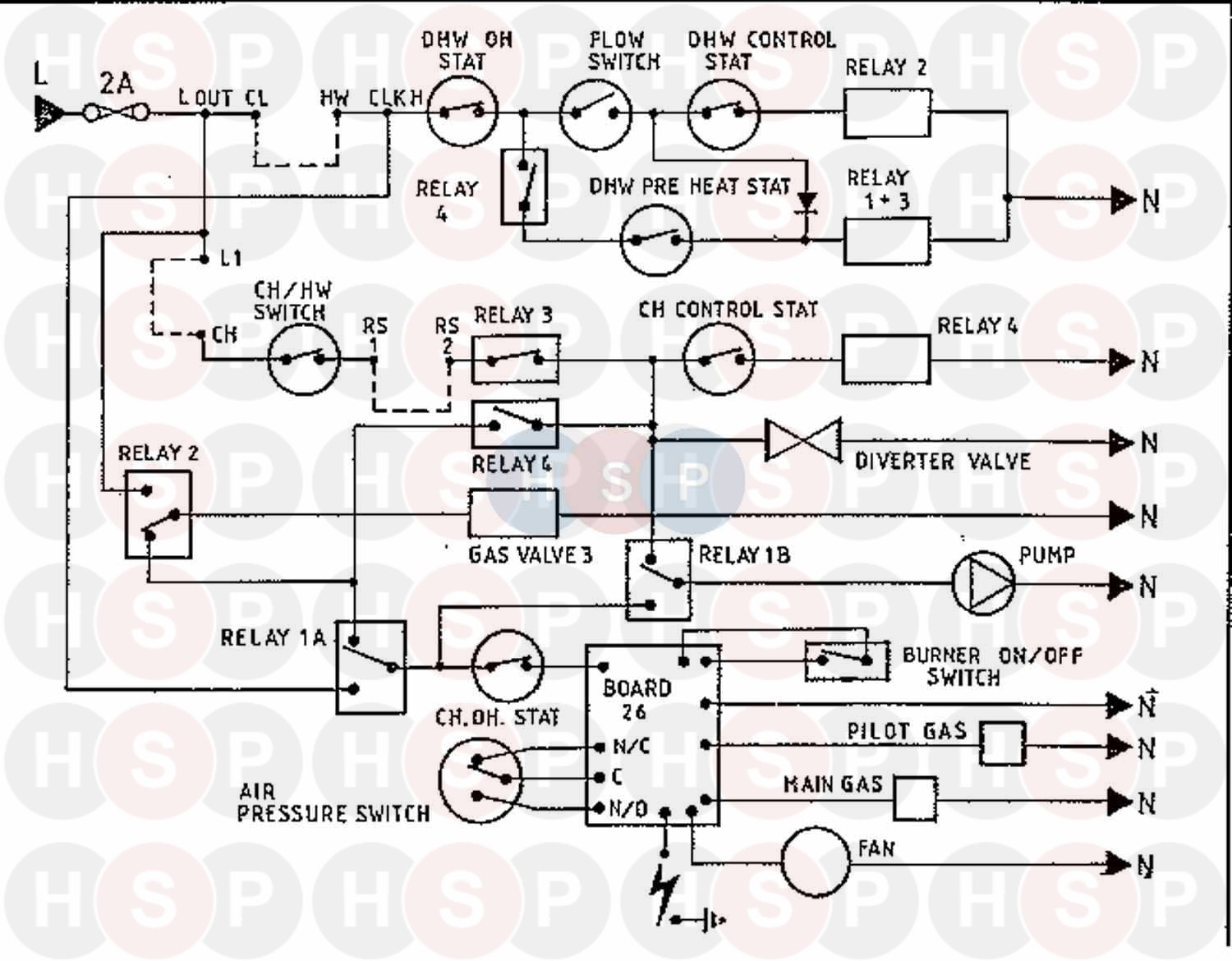
Ideal Concord Wlx Cf 60 Wiring Diagram 4 Diagram Heating Spare Parts
Ideal Classic Combi Nf80 Wiring Diagram 1 Diagram Heating Spare Parts
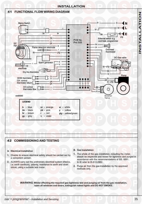
Ideal Isar He35 Functional Flow Wiring Diagram Diagram Heating Spare Parts

Hive Dual Channel On A Combi Boiler Overclockers Uk Forums