Contractor Connection Single Phase Motor Starter Wiring Diagram Pdf

The Complete Guide Of Single Phase Motor Wiring With Circuit Breaker And Contactor Diagram Electrical Circuit Diagram Circuit Diagram Electrical Wiring Diagram

Single Phase Motor Contactor Wiring Electrical Wiring Electrical Engineering Electricity

Single Phase Motor Contactor Wiring Diagram In Urdu Hindi Youtube

Phase Controller Wiring Phase Failure Relay Diagram Electrical Wiring Electrical Panel Wiring Electrical Projects

Wiring Diagram For 220 Volt Submersible Pump Single Phase Motor Starter Wiring Diagram Pdf Si In 2020 Electrical Circuit Diagram Circuit Diagram Home Electrical Wiring

Contactor Wiring Guide For 3 Phase Motor With Circuit Breaker Overload Relay Nc No S Electrical Circuit Diagram Electrical Projects Electrical Wiring Diagram

With single phase motor with capacitor forward and reverse wiring.
Contractor connection single phase motor starter wiring diagram pdf. A repulsion electric motor is by definition a single phase motor which has a stator winding arranged for connection to the source of power and a rotor winding connected to a commutator. Single phase motor wiring diagram forward reverse collections of phase meter wiring diagram single phase motor capacitor wiring. Wiring diagram for single phase motor fresh pretty single phase. Single phase submersible motor starter wiring diagram explanation.
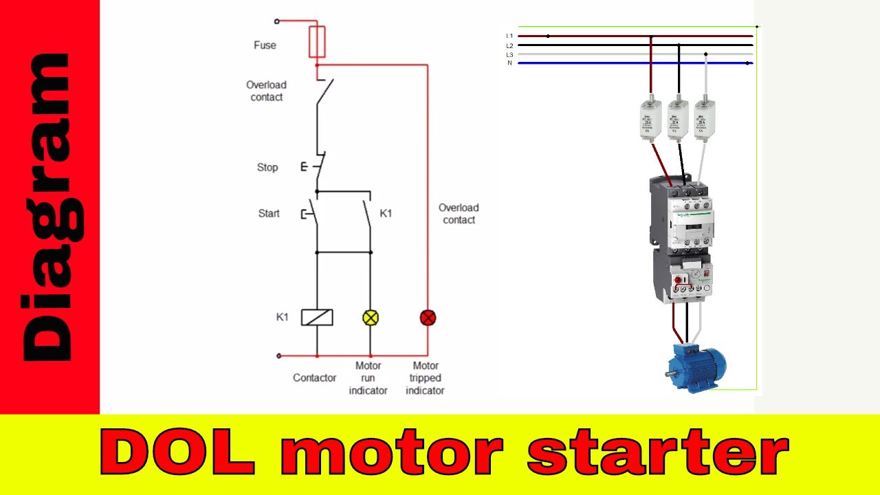
The direct on line motor starter dol is designed to switch a single or three phase induction motor at rated voltage. Dol starter wiring diagram for three phase motor to wire a 3 phase motor the first thing to wire is a circuit breaker which is disconnect and connecting point then we will get the supply from circuit breaker and connect supply to contactor or starter and then to overload relay. Each component ought to be placed and linked to different parts in particular manner. 1 2 2kw motor with a flc of 5 amps 415volts.
Table 11 ratings for 120 240 v 3 wire single phase dwelling. Ac blower motor wiring diagram furthermore 3 phase star delta motor connection diagram besides dc electrical motor wiring diagram further 813 tube lifier schematic furthermore three phase induction motor rotor and stator. How to wire a contactor and. Electromagnetic contactor which can be opened by the thermal overload relay under fault conditions.
Single phase motor wiring diagram with capacitor sources. In the above one phase motor wiring i first connect a 2 pole circuit breaker and after that i connect the supply to motor starter and then i do cont actor coil wiring with normally close push button switch and normally open push button switch and in last i do connection between capacitor. Brushes and commutators are short circuited and are placed so that the magnetic axis of the rotor winding is inclined to the magnetic axis of the stator winding. The thermal overload is supplied as a separate item.
The simplest form of motor starter for the induction motor is the direct on line starter. 29 best submersible pump images on pinterest. Single phase motor wiring diagram with capacitor baldor single phase motor wiring diagram with capacitor single phase fan motor wiring diagram with capacitor single phase motor connection diagram with capacitor every electrical arrangement is made up of various unique pieces. Single phase submersible pump starter wiring diagram gallery amazing single phase water pump control panel wiring diagram frieze.
Table 5 motor lead connections 64 table 6 enclosures for non hazardous locations 99. Wiring diagram book a1 15 b1 b2 16 18 b3 a2 b1 b3 15 supply voltage 16 18 l m h 2 levels b2 l1 f u 1 460 v f u 2 l2 l3 gnd h1 h3 h2 h4 f u 3 x1a f u 4 f u 5 x2a r power on optional x1 x2115 v. 3 wire submersible pump wiring diagram wellread. The direct on line motor starter dol consist a mccb or circuit breaker contactor and an overload relay for protection.

Https Encrypted Tbn0 Gstatic Com Images Q Tbn 3aand9gctb2amp2ohuxjyah9stancncwrgzpx4vu Cow Usqp Cau

Single Phase Submersible Pump Starter Wiring Diagram Gooddy Org Best Of Submersible Pump Submersible Electrical Circuit Diagram

Magnetic Contactor Wiring Diagram Pdf Electrical Wiring Electrical Panel Wiring Electrical Projects

Single Phase Motor Control Wiring Diagram Electrical Engineering World Line Diagram Electrical Diagram Electricity
Wiring Diagram For Two Speed Motor 3ph 2 Speed Motor Youtube

Single Phase Submersible Pump Starter Wiring Diagram On Water Control Panel Inside To Submersible Pump Submersible Electrical Circuit Diagram
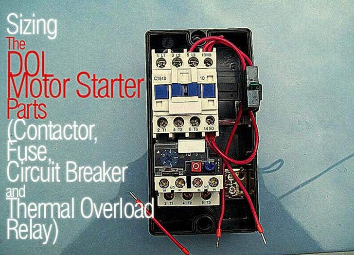
Sizing The Dol Motor Starter Parts Contactor Fuse Circuit Breaker And Thermal Overload Relay

Three Phase Dol Starter Wiring Diagram With Mccb Contactor Electrical Wiring Electrical Circuit Diagram Home Electrical Wiring

Electrical Engineering World Electrical Wiring Electrical Engineering Electricity

Single Phase Motor Starter With Timer Diagram Single Phase Motor Timer Youtube

New Wiring Diagram Of Auto Transformer Starter Diagram Diagramtemplate Diagramsample Auto Transformer Diagram Transformers
How To Wire A Contactor And Overload Direct Online Starter Youtube

Forward And Reverse Motor Starter Wiring Diagram Elec Eng World Electrical Circuit Diagram Circuit Diagram Electrical Diagram


