Traffic Signal Cabinet Wiring Diagram

Traffic Signal Plc Ladder Programming Complete Project Popular Plc Videos In Automation Design And Development Ladder Logic Traffic Light Traffic Signal

Wiring Diagram For Traffic Light Controller Circuit Model Trains Ho Model Trains Model Train Layouts

4 Way Traffic Lights Diagram Electronic Schematics Traffic Light Electronic Circuit Projects

Econolite Traffic Signal Controller Cabinet Nema

Traffic Lights For Model Cars Or Model Railways Circuit Diagram Model Railway Model Trains Traffic Light
Ppt Traffic Signals 101 Powerpoint Presentation Free Download Id 5504447
A wiring diagram is a straightforward visual representation with the physical connections and physical layout of an electrical system or circuit.
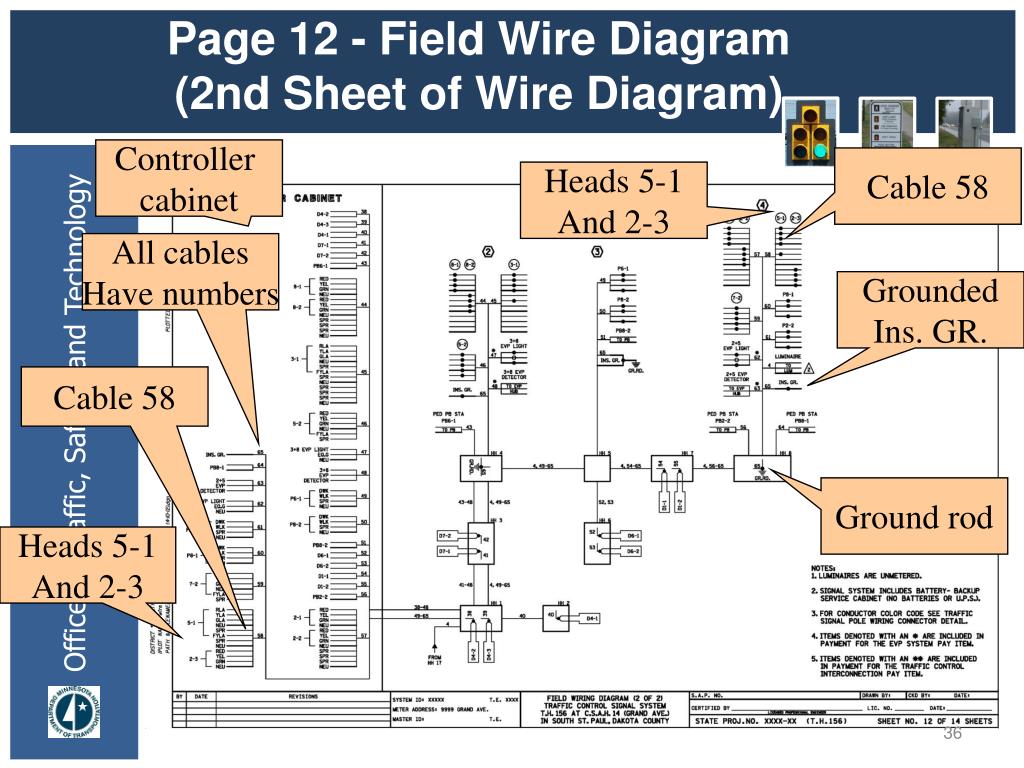
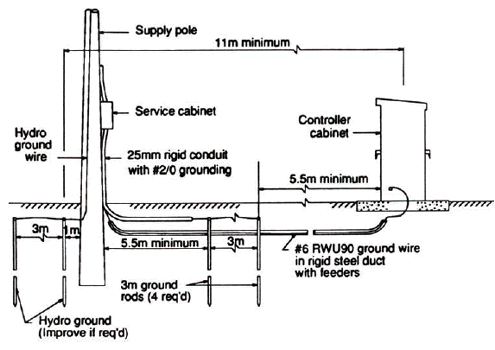
Traffic signal cabinet wiring diagram. Different and i will use a new diagram to explain. A minimum of 20 spare terminals shall be provided on all terminal strips. Conduit wires 2 12 c 14 1 3 c 14 5 2 c 14 1 3 c 20 1 6 pr 19 1 1 c 6 ins. Econolite part model vehicle a cabinet wiring diagram for the model and cabinets shown complete on a single nema ts2 sensors shall have the channel status outputs disabled.
It reveals the elements of the circuit as simplified forms as well as the power and signal links between the tools. Variety of traffic signal cabinet wiring diagram. Indications read right to left. Topics will include the explanation of the design and set up of a traffic signal cabinet and the methods used.
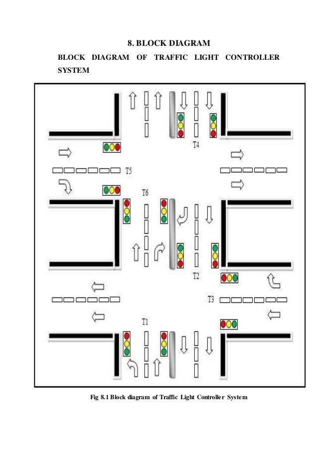
Types of traffic signal cabinetsts2 type 1 plug n go modular cabinet assembly wiringall. Seen mainly in ts 2 cabinets. Gr pole notes loop detector detector chart construction notes. 4 1 traffic control signal plan traffic control signal plans are prepared on 11 x 17 plan sheets.
Zero flex and completely weather proof thinking inside the ntcip box. A wiring diagram is a streamlined conventional pictorial representation of an electric circuit. Traffic signal cabinet wiring diagram what is a wiring diagram. It shows what sort of electrical wires are interconnected which enable it to also show where fixtures and components might be.
It shows the elements of the circuit as simplified shapes as well as the power as well as signal links in between the gadgets. The scale is indicated on the individual layout sheets. Traffic signal troubleshooting charles devitis upper merion township traffic signal supervisor december 6. Signal layout page 5 road lines conduit ped diagram and phasing signal face chart scale pole numbering starts at the cabinet going clockwise.
Assortment of traffic signal cabinet wiring diagram. 1 duplex nema r ground fault interrupt equipment receptacle item m nema traffic signal cabinet type m item m nema traffic signal cabinet type p38 page 4 of 7 01 29 01 phase in consecutive order as follows. In this chapter the items found in typical standalone traffic control signal and lighting plans will be presented. Econolite part model vehicle a cabinet wiring diagram for the model and cabinets shown complete on a single nema ts2 sensors shall have the channel status outputs disabled.
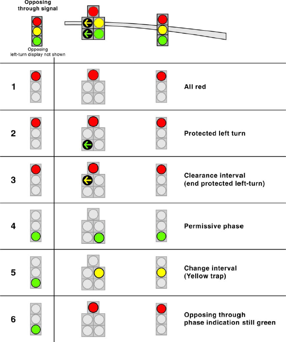
If used for vehicle phasing. R1 a1 g1 dw1 w1 r2 a2 g3 etc. Phases 2 4 6 and 8 are parent phases. Learn how to troubleshoot and recognize.
Https Www Mesaaz Gov Home Showdocument Id 8102

Pin On Electronic Circuits

Density Based Traffic Signal System Using Microcontroller Traffic Signal Lighting Control System Microcontrollers
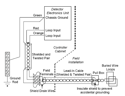
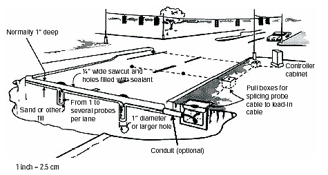
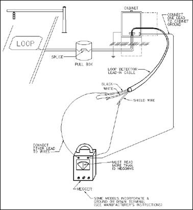
Traffic Detector Handbook Third Edition Volume Ii Fhwa Hrt 06 139
Traffic Signal Systems A Review Of Current Technology In The United States

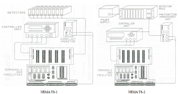
Traffic Control Systems Handbook Chapter 7 Local Controllers Fhwa Office Of Operations
Traffic Detector Handbook Third Edition Volume Ii Fhwa Hrt 06 139
632 Traffic Signals And 633 Signal Controllers
Traffic Signal Timing Manual Chapter 4 Office Of Operations

Traffic Light Control System Using Microcontroller
Design Of Fpga Based Traffic Light Controller System

Control Of Traffic Light Ladder Logic Diagram Ladder Logic Programmable Logic Controllers Plc Programming
Chapter 2 Traffic Detector Handbook Third Edition Volume I Fhwa Hrt 06 108

