Simple Dc Motor Circuit Diagram

How To Build The Simplest Dc Motor Speed Controller Using Potentiometer And Mosfet Updated Youtube Motor Speed Circuit Diagram Electronics Mini Projects

How To Build The Simplest Dc Motor Speed Controller Using Potentiometer And Mosfet Updated Youtube Motor Speed Circuit Diagram Electronics Mini Projects

Very Simple 12v Motor Speed Controller With E555 Timer Motor Speed Circuit Diagram Circuit

How To Make An Universal Dc Motor Speed Controller Electronics Mini Projects Electronics Projects Diy Electronic Circuit Projects

Speed Control Of Dc Motor Circuit Diagram In 2020 Circuit Diagram Electronic Circuit Projects Electronic Schematics

Tutorial Simple Dc Motor Speed Control Circuit How To Make An Univers Motor Speed Circuit Hobby Electronics
P55n mosfet you can use any mosfet 50k potentiometer 10k resistor 12 volt power supply circuit diagram.
Simple dc motor circuit diagram. Four point manual dc motor starter circuit diagram. The design of a simple motor speed controller using pwm may be understood as follows. Question 1 how is it possible to electrically measure the torque output by a permanent magnet dc motor. When it comes to controlling motor speed uniformly and efficiently a pwm based controller becomes the ideal option here we will learn more regarding a simple circuit to implement this operation.
In this post we learn how to make a simple 3 phase brushless dc motor driver circuit. An automatic starter operates in a similar fashion except that automatic relays short out sections of the starter resistance either by a time sequence or when the armature current drops to a selected value. The circuit employs the popular irs2330 3 phase driver ic the presented idea looks simple since most of the technicalities is taken care of efficiently by the ic itself it s all about connecting the relevant pinouts with the few external supplementary. Pwm dc motor control with ic 555.
It is very simple and for large electric motors it involves the use of a shunt resistor modify this circuit diagram to include a meter that provides indirect indication of motor torque.

How To Build A Simple Pwm Dc Motor Speed Controller Using Atmega8 Microcontroller Mosfet And Electronic Circuit Design Electrical Circuit Diagram Dim Lighting

Dc Motor Control Circuit Diagram Electrical Engineering Blog Circuit Diagram Electrical Circuit Diagram Electronic Circuit Design

How To Build A Simple Pwm Dc Motor Speed Controller Using Atmega8 Microcontroller Mosfet And Pot Youtube Motor Speed Microcontrollers Electronics Circuit

Pwm With Forward And Reverse Finally Dc Motor Speed Controller Simple Circuit Electronics Circuit Electronic Circuit Projects Electronic Circuit Design
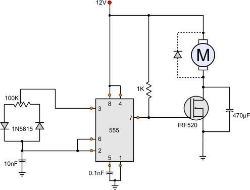
555 Dc Motor Speed Control Motor Speed Circuit Diagram Circuit

Pwm With Forward And Reverse Finally Dc Motor Speed Controller Simple Circuit Yout Electrical Engineering Projects Electronic Schematics Simple Circuit

Pwm With Forward And Reverse Finally Dc Motor Speed Controller Simple Circuit Electronic Circuit Projects Simple Electronic Circuits Electronics Circuit

Ne555 Dc Motor Speed Controller Circuit Diagram Motor Speed Circuit Electronic Circuit Projects

Solder Iron Controller Light Dimmer Ac Motor Speed Controller Electronic Circuit Design Electrical Circuit Diagram Dim Lighting

How To Build A Simple Pwm Dc Motor Speed Controller Using Atmega8 Microcontroller Mosfet And Pot Youtube Motor Speed Microcontrollers Circuit Diagram

3 Simple Dc Motor Speed Controller Circuits Explained In 2020 Motor Speed Circuit Speed

Rf Wireless Pwm Dc Motor Speed Controller Circuit Diagram Motor Speed Wireless Circuit Diagram

Simple Circuit To Control Dc Motor On Off Simple Circuit Electronic Schematics Electronics Workshop


