Motorised Valve Hive Dual Channel Wiring Diagram

Boiler Wiring Diagram For Thermostat To Y Plan Hive New Central And Heating S In Boiler Wiring Diagram Central Heating System Central Heating Heating Systems

Unique Wiring Diagrams S Plan Heating Systems Diagram Diagramsample Diagramtemplate Heating Systems Central Heating System Thermostat Wiring
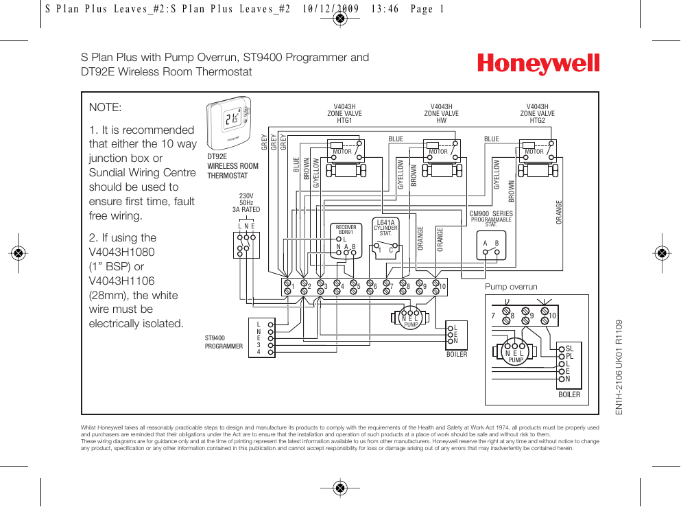
Diagram S Plan Plus Wiring Diagram Full Version Hd Quality Wiring Diagram Pregboardwiring Concessionariabelogisenigallia It

3 Phase Wiring Diagram For House Http Bookingritzcarlton Info 3 Phase Wiring Diagram For House Thermostat Wiring Heating Systems Central Heating System
Wiring Hive On Worcester Bosch Greenstar 25 Si Or 30 Si Diynot Forums

Central Heating Y Plan Wiring Diagram Arc Welder Wiring Diagram Color For Wiring Diagram Schematics
S plan wiring centre cylinder thermostat hot water time clock auto bypass valve motorised zone valves and pipe stats are available if requested.
Motorised valve hive dual channel wiring diagram. Yours is the only diagram that says how to do it. Power starts at terminal 4 ch on in the programmer. This causes the valve motor to move to the mid position and water from the boiler flows to both the hot water cylinder and the radiators. V4043 motorised zone valve the v4043 series of two port motorised valves has a wide range of flow control applications in domestic and light commercial central heating systems.
Dual channel the hive receiver is double insulated so doesn t receiver need an earth connection. Bs7671 iee wiring regulations part p of the building regulations and any relevant technical operational procedures. 11 02 2017 at 19 14. How a mid position valve operates within a y plan heating system how a w plan heating system operates faq pump overrun wiring diagrams for s plan incorporating a st9400 programmer.
I m changing my system boiler to a combi and would like to use my existing hive dual channel. Our wiring diagrams section details a selection of key wiring diagrams focused around typical sundial s and y plans. You ll find a tether on the for conventional backplate to secure an earth wire if needed. As with hot water only the orange valve wire is connected to power via the wiring centre terminal 8 but orange is still not connected to anything inside the valve.
The v4043h normally closed models have end switches for electrical control of pump and or boiler. Dual channel receiver wiring. This passes via the wiring centre terminal 4 to the room thermostat. The h box wiring centre is used to switch on a shunt pump which will send primary water from a buffer tank or the heatpump itself to the manifolds.
Once the valve is fully open a switch inside connects the grey and orange wires together.

Unique Honeywell T6360b Room Thermostat Wiring Diagram Diagram Diagramsample Diagramtemplate Wirin Thermostat Wiring Central Heating Central Heating System

Central Heating Wiring Diagram S Plan Diagram Base Website S Plan Venndiagram Aisc Net It

Contactor Wiring Diagram With Timer Unique Cutler Hammer Relay Wiring Diagram Wiring Diagram Timer Diagram Relay

99 Civic Engine Harness Wiring Diagram And Civic Engine Diagram Wiring Schematic Diagram In 2020 Car Alarm Honda Civic Honda Civic Headlights

Pioneer Avh X1500dvd Wiring Diagram In Free Harness D16z6 On At In 2020 Diagram Wire Layout

Hive Multizone S Plan Wiring Diynot Forums

Electrical Wiring Jvc Car Stereo Wire Harness Diagram Audio Wiring Head Unit P Jvc Radio Wire Harness 81 Wirin Media Room Design Sony Car Stereo Car Stereo
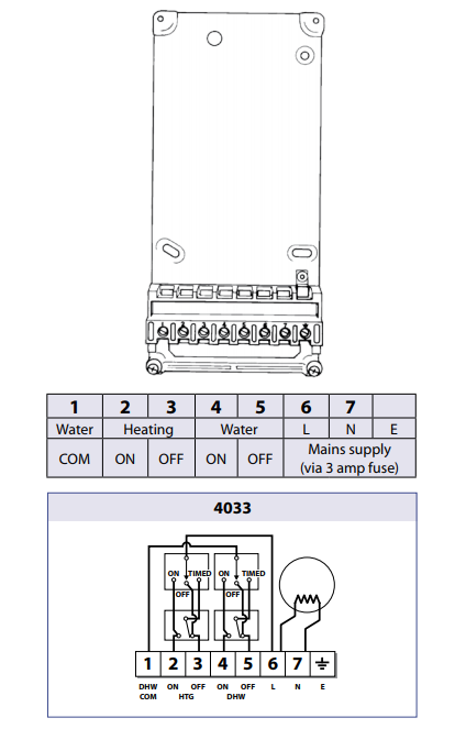
Replace Randall 4033 With Hive Have I Got The Wiring Right Diynot Forums

Amplifier Wiring Diagrams How To Add An Amplifier To Your Car Audio System Subwoofer Wiring Car Audio Systems Car Audio Installation

737 3 500 Air Conditioning Schematic Www B737 Org Uk Boat Wiring Electrical Wiring Diagram Car Air Conditioning

Car Amplifier Wiring Diagram Installation Http Bookingritzcarlton Info Car Amplifier Wiring Diagram In Car Amplifier Sound System Car Car Audio Installation

W1 W2 E Hvac School

Electric Ezgo Golf Cart Wiring Diagrams Ezgo Golf Cart Electric Golf Cart Golf Carts


