Havells Timer Switch Connection Diagram
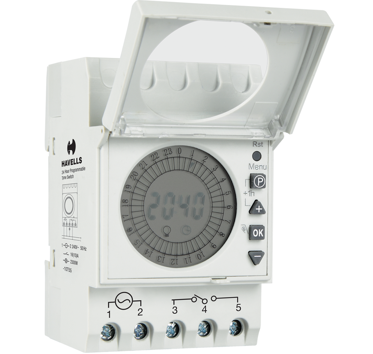
Digital Programmable Time Switch 24 Hour

Havells Timer Switch At Rs 2350 Piece Timer Switch Id 16464910712
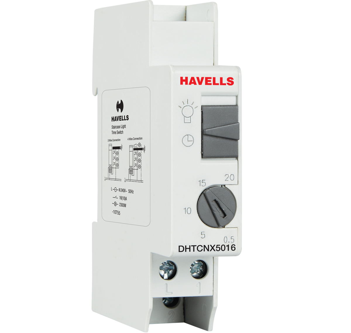
Staircase Light Time Switch 0 5 20 Min
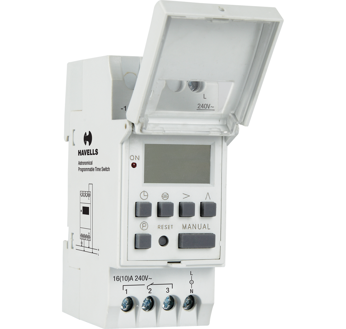
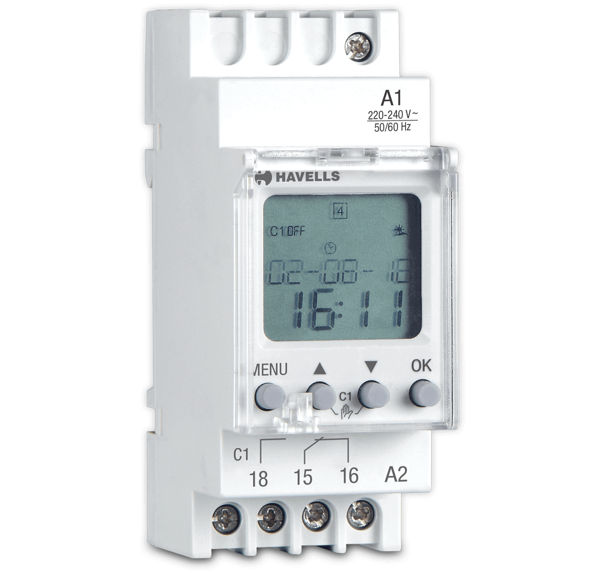
Astronomical Weekly Programmable Time Switch

Tamil 24 Hrs Timer Switch Connection Diagram New Explaining Youtube
Time Switch Electronic Timer Switches Havells India
In which i done all the connection.
Havells timer switch connection diagram. Havells premium electric switches and boxes are aesthetically designed perfect to complement your walls. The line connection is where the incoming hot wire from the power source is connected while the load connection carries power onward from the switch to the appliance or device. 10 2 10 cashback on visa. 24hrs timer switch in explaining in tamil and circuit diagram also very simple method how to website category mechanical timers how to setup a timer ins.
In the above manual changeover switch wiring diagram i shown the incoming supply from the energy meter incoming supply form the portable generator and out going supply to load or house load. In this tutorial we will show the star delta y δ 3 phase induction ac motor starting method by automatic star delta starter with timer with schematic power control and wiring diagram as well as how star delta starter works and their applications with advantages and disadvantages. In the diagram i shown handle type manual changeover switch. By havells 450 460.
If the ends on the wires are worn cut them off and strip them the insulation of the ends for a fresh connection. Automatic star delta starter with timer for 3 phase ac motors. It is very useful to get on and off the bulbs lamps in proper time. Attach timer switch wires.
Our electrical switches come with best technology for reliability quality durability. In fig 2 different connection and wiring diagrams are shown for a two pole single phase manual changeover switch. Strip 1 2 inch of insulation from the black wire on the incoming cable delivering power from the source and insert the end of this wire into the screw terminal. Havells range of time switches used to control the opening and closing of electrical circuits based stairwell lighting in multiplexes hotels offices etc.
5 off with hsbc cashback card. The wires may attach directly to the switch with screws or the switch may have short. The upper portion of the changeover switch is directly connected to the main power supply while the lower first and right connections slots are connected to the backup power supply like generator or inverter.

G0rmvkerdbp9em
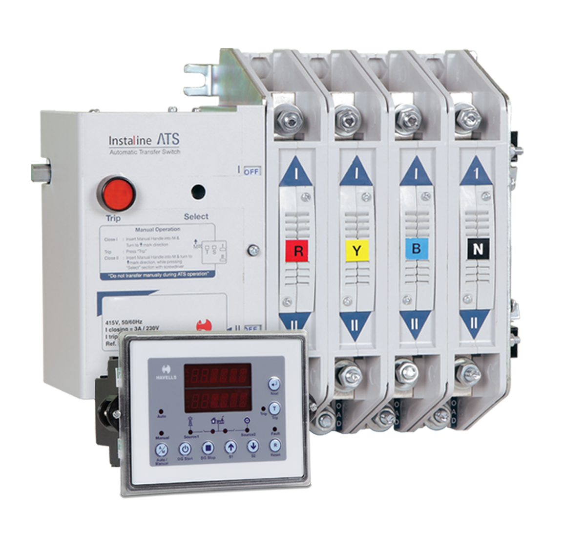
Four Pole Instaline Automatic Transfer Switch From 400a 630a
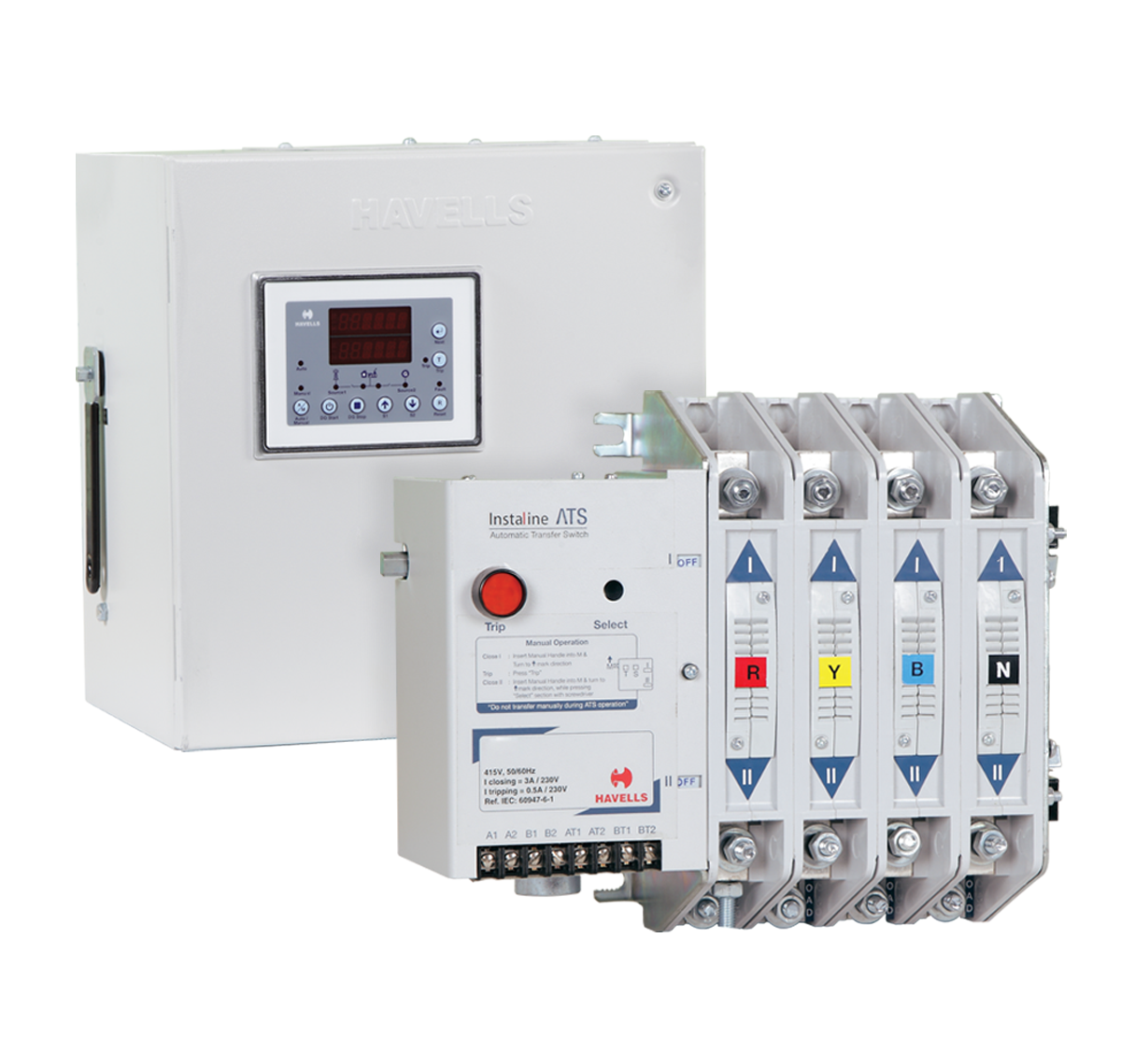
Instaline Automatic Transfer Switch From 100a 160a In Three Pole

Havells Accl Automatic Changeover Current Limiter For Smart Cities Youtube

Havells Urja Single Phase Submersible Pump Controller At Rs 2753 Piece Noida Id 20668164730

Havells Onload Changeover Switch 4 Pole 63 Amp 415 Volt Ihcnfo0063 Bestomart

Offers You Can T Refuse On Havells Staircase Light Time Switch Electrikals Com Switches Light Switch
Switchgear Electrical Switchgear Medium Voltage Switch Gear Havells India
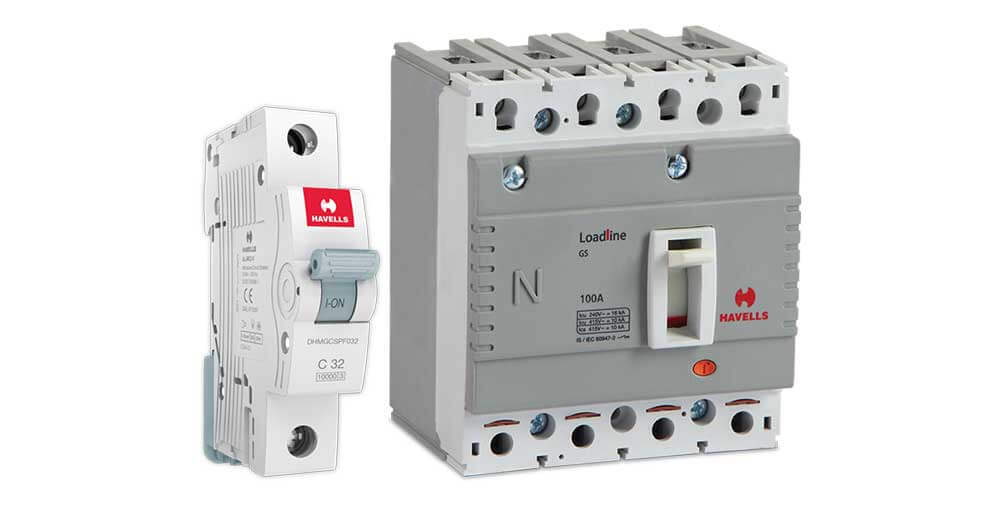
What Is The Difference Between Mcb And Mccb Havells India Blog

How To 100 Amp Change Over Connection Point Connection Point Continuity Chek 100 Amp Changeover Youtube

Buy Havells Mcb Changeover Dp Pvc Plastic Base Model White Online At Low Prices In India Amazon In
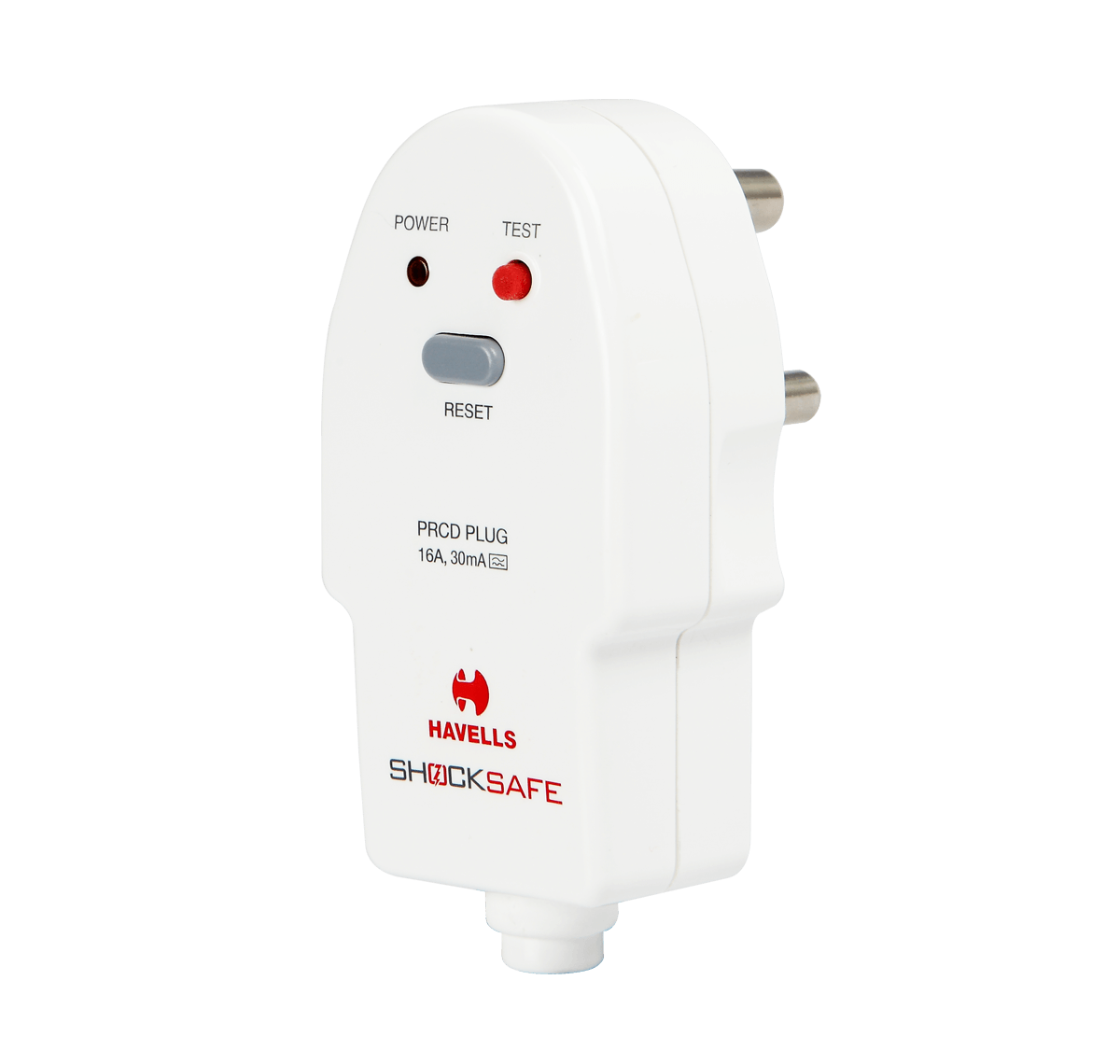
Prcd Plug

Buy Havells Dhadosn3012 3 Module Spn Accl Pvc Plastic Base Model White Online At Low Prices In India Amazon In


