Fan Cycling Switch Wiring Diagram

14 Automatic Wiring Diagram For Ceiling Fan Ceiling Fan Switch Ceiling Fan Wiring Ceiling Fan Pull Chain

Imperial Electric Fan Relay Wiring Diagram Electric Fan Conversion Electricity Automotive Electrical Electrical Circuit Diagram
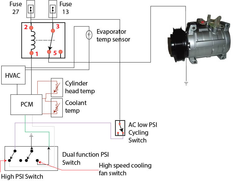
Fan Control

Hot Topics What S Wrong With My A C Doityourself Com Ceiling Fan Wiring Ceiling Fan Switch Fan Motor

Delay Timers And The Air Conditioner Condenser Quality 101

Ceiling Fan Switch Wiring Ceiling Fan Switch Ceiling Fan With Light Ceiling Fan Wiring

For the switch that you have removed from the fan with the purple wire in the l position you cannot purchase a replacement switch at the big box stores.
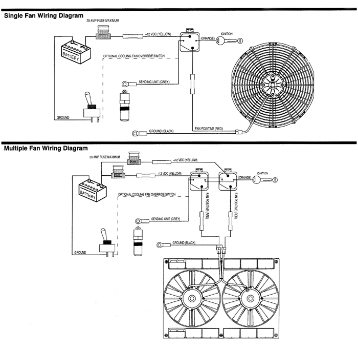
Fan cycling switch wiring diagram. Accelerated to 2 sec. See wiring diagram alarm circuit the onboard alarm is a dry set of nc contacts which closes to indicate an alarm. Switched outlet wiring diagram. If ambient is below 50 f may need to addd pressure fan cycling switch.
Wiring diagrams 25hbc3 baset series heat pump with puronr refrigerant 11 2to5nominaltons legend jumpered test pins use metal object field speed up cycle heat cycle. Get the 10 gauge wire and place it through the hole in your fire wall. The white wire is your neutral wire the copper wire is the grounded wire and the black wire powers the fan. Black speed switch three wire capacitor.
Field selected time period between defrost. Type and wiring for the alarm is customer specified. 1 to l and c1 1 2 med. Ceiling fan wiring diagram 1.
Now take the power wire from your fan and connect it to the wire that is going through the firewall. Speed switch connection table. View all posts by saum hadi. The switches you get there cycle through l connected to 1 then l connected to 2 then l connected to 3.
Jan 24 18 02 09 pm. Jan 24 18 02 26 pm. Some setups will also have a blue wire which powers the lights on your fan. This is a simple illustrated circuit diagram of ceiling fan to be noted that the wiring diagram is for ac 220v single phase line with single phase ceiling fan motor.
Sometimes it is handy to have an outlet controlled by a switch. 1 to l and c1 2 3 slow. Wrg 4500 12 volt cooling fan relay wiring diagram cooling fan wiring diagram basic electrical cooling fan switch wiring diagram library painless wiring fan relay diagram general 48 volt battery wiring diagram diagrams. Black speed switch with only three terminals connected two wire capacitor.
Published by saum hadi. 3ø wiring diagrams 1ø wiring diagrams diagram er9 m 3 1 5 9 3 7 11 low speed high speed u1 v1 w1 w2 u2 v2 tk tk thermal overloads two speed star delta motor switch m 3 0 10v 20v 415v ac 4 20ma outp uts diagram ic2 m 1 240v ac 0 10v outp ut diagram ic3 m 1 0 10v 4 20ma 240v ac outp uts these diagrams are current at the time of publication. Ceiling fan wiring diagram 2. I just went through this 11 2019 and have a clear but unusual answer.
Step by step instructions on how to wire a switched outlet. Wire a switched outlet. There should be a white copper or green and black wire coming out of the ceiling s electrical box. This will be the wire that connects your switch to your fan power wire.
Here a simple spst switch is used to supply power or not to the fan motor and a regulator is used to controlling the fan speed. Want to turn a lamp on with a light switch.

Wiring Diagram For Ceiling Fan Switch Bookingritzcarlton Info Fan Light Switch Light Switch Wiring Bathroom Fan

Wiring Diagram For Ceiling Fan Switch Bookingritzcarlton Info Ceiling Fan Switch Ceiling Fan Wiring Ceiling Fan Light Kit

Electric Fans With Relay Wiring Electricity Automotive Mechanic Electric Fan

Using Defrost Termination And Fan Delay Controls

14 Automatic Wiring Diagram For Ceiling Fan Ceiling Fan Wiring Ceiling Fan Installation Ceiling Fan With Remote
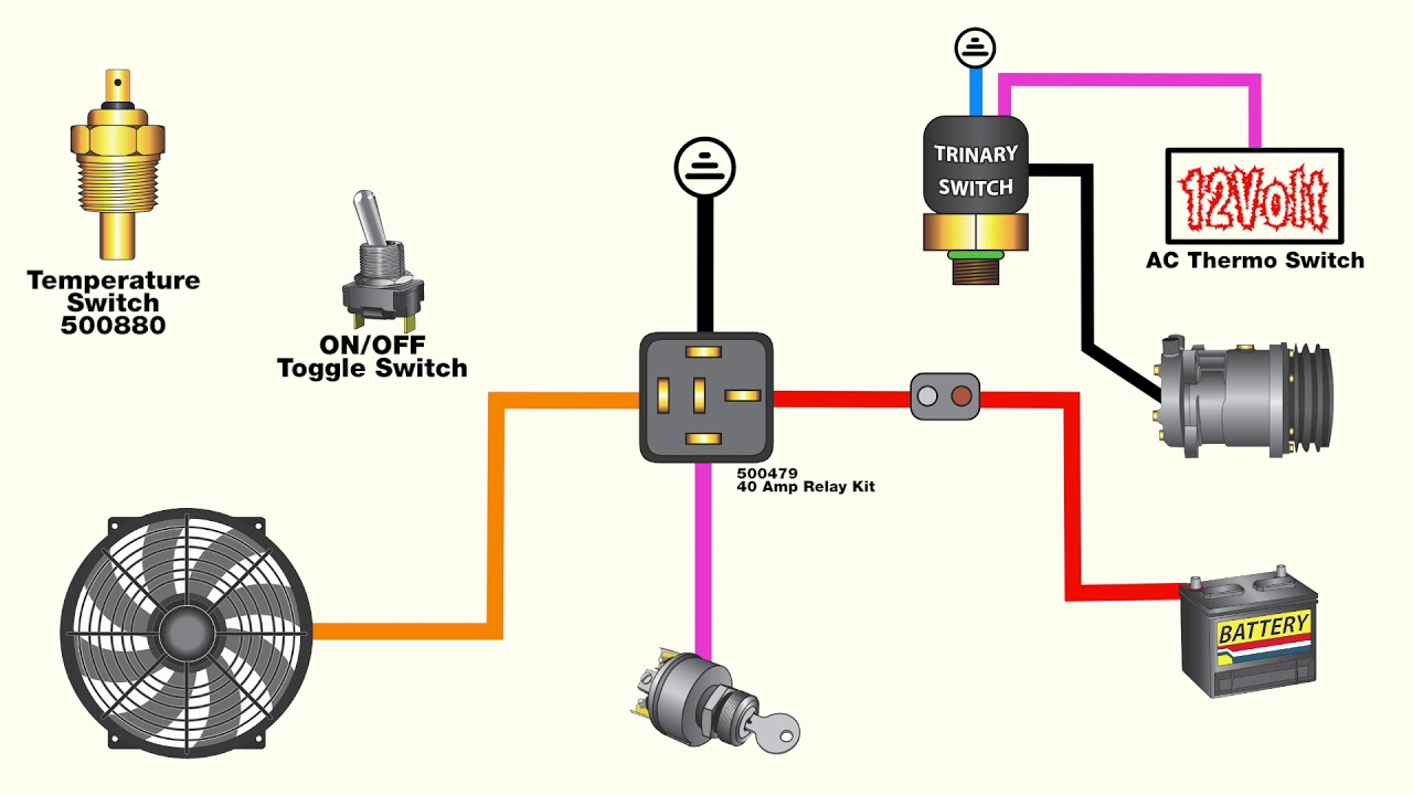
How To Wire An Electric Fan With An Ac Trinary Switch Youtube

Wiring For Bathroom Fan And Light Switch Fan Light Switch Ceiling Fan Wiring Light Switch Wiring

Pin By Juan Aguirre On 777 Electric Cooling Fan Electric Cooling Electricity
Ac Switch Wiring Diagram Harness Rostra Wire Bmw 5l4oe Deviille Deco Doe3 Decorresine It

25 Wiring Diagram For 3 Way Switch Ceiling Fan Bookingritzcarlton Info Ceiling Fan With Light Ceiling Fan Wiring Ceiling Fan Pulls
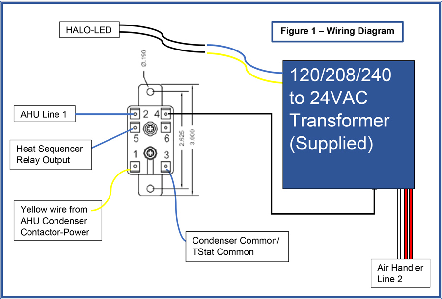
Relay Switch Instructions Rgf

Hunter Ceiling Fan Switch Wiring Diagram In 2020 Hunter Ceiling Fans Ceiling Fan Switch Ceiling Fan Wiring

19 Simple Kinetic Honda Wiring Diagram Ideas Https Bacamajalah Com 19 Simple Kinetic Electrical Wiring Diagram Trailer Wiring Diagram Trailer Light Wiring

