Electronic Component Schematic Symbols
Circuit Schematic Symbols Electrical Schematic Symbols Electrical Symbols Circuit Diagram

Basic Electronic Symbols Electrical Symbols Electronic Schematics Symbols

Schematic Symbols

Schematic Symbols Chart Symbols Chart 1 3 Electrical Symbols Electrical Circuit Diagram Electrical Diagram

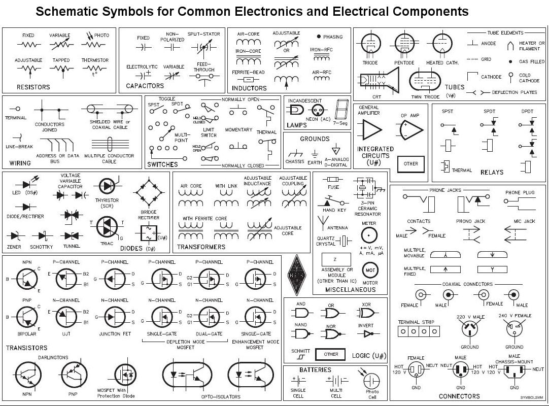
Common Electronics Component Schematic Symbols Symbols Electronics Electronics Components

Diagram Wiringdiagram Diagramming Diagramm Visuals Visualisation Graph Electrical Schematic Symbols Electrical Circuit Diagram Electrical Wiring Diagram

This is an australian standard for electronic component symbols.
Electronic component schematic symbols. The symbols represent electrical and electronic components. The database includes around 1750 circuit symbols overall. This ieee standard for circuit symbols has various release dates. A resistor is used to restrict the amount of current flow through a device.
Circuit symbols are used in circuit diagrams showing how a circuit is connected together. Circuit symbols of electronic components. Symbols even more the electronic components have terminals and each will have its own name and polarities. The basic is passive and.
The actual layout of the components is usually quite different from the circuit diagram. Applicable in controlling lamp brightness capacitor charge rate etc. The symbols are very important to represent electronic components in a circuit diagram without electronic symbol the design of circuit and schematics are very difficult and also knowing the components is very must to read the circuit diagram representation. Component circuit symbol function of component push switch push to make a push switch allows current to flow only when the button is pressed.
Push to break switch this type of push switch is normally closed on it is open off only when the button is pressed. To build a circuit you need a different diagram showing the layout of the parts on breadboard for temporary circuits stripboard or printed circuit board. The symbol for a battery is shown below. Australian standard as 1102.
To be able to read schematics you must know the schematic symbols. This is the switch used to operate a doorbell. Hence i have enlisted symbols of only the basic and mostly components. This article gives some of the frequently used symbols for drawing the circuits.
An electronic symbol is a pictogram used to represent various electrical and electronic devices or functions such as wires batteries resistors and transistors in a schematic diagram of an electrical or electronic circuit these symbols are largely standardized internationally today but may vary from country to country or engineering discipline based on traditional conventions. There are many electrical and electronic schematic symbols are used to signify basic electronic or. A large and a small line is suppose to represent one battery cell so that the image below would suggest a two cell battery of 3 v. Here is an overview of the most used symbols in circuit diagrams.
Electrical symbols or electronic circuits are virtually represented by circuit diagrams. This standard for electronic component symbols is the american one and is also known as ieee std 315. There are so many electronic components that it is not possible to mention symbols of all the components in this one single tutorial. Electrical symbols electronic symbols.

Basic Electronics Symbols Electrical Symbols Electronic Schematics Symbols

Schematic Symbols For Electronic Components Circuit Electronic Schematics Electronic Components

Schematic Symbols Chart Wiring Diagram Database Wiring Drafting Symbols Electrical Schematic Symbols W Electrical Schematic Symbols Electronics Circuit Circuit

Pin By Sherrie Costello Reed On Symbols Electronics Components Electrical Circuit Diagram Electrical Symbols

Electronic Component Schematic Symbols Input Jacks Power Supplies And Antennas Electronic Schematics Electronics Components Diy Electronics

9m2pju Circuit Symbols Electronic Engineering Electronics Basics Electronic Schematics
Wiring Diagram Symbols Bookingritzcarlton Info Electronic Schematics Electronics Basics Electric Circuit

Basic Schematic Symbols Electrical Engineering Books Electronic Schematics Electronic Engineering Electronics Circuit

Circuit Symbol Circuit Schematic Symbols Of Electronic Components Circuit Electronic Engineering Electronic Components

Electronics Symbols Components And Circuit Diagram Reading In Hindi Urdu Youtube Electrical Symbols Symbols Electronics Components

Electrical Symbols 11 Electrical Symbols Basic Electrical Wiring Electronic Engineering

More Electrical Symbols Electrical Schematic Symbols Circuit Electronic Schematics

Circuit Schematic Symbols Diodes Diode Electronics Circuit


