Electrical Tube Light Connection Circuit Diagram

Wiring Diagram Of Single Tube Light Installation With Electromagnetic Ballast Tube Light Light Switch Wiring Lighting Diagram

Connection Of Tube Light In 2020 Tube Light Tube Connection

Led Fluorescent Tube Wiring Diagram Bookingritzcarlton Info Led Fluorescent Tube Led Fluorescent Fluorescent Tube

Wiring Diagram For A Single Tube Light Circuit Tube Light Circuit Diagram Circuit
Tube Wiring Diagram Http Bookingritzcarlton Info Tube Wiring Diagram Led Fluorescent Tube Led Fluorescent Led Fluorescent Light

Connection Of Tube Light Tube Light Fluorescent Tube Light Tube

Connection of one or more luminaire points lights controlled by a simple switch.
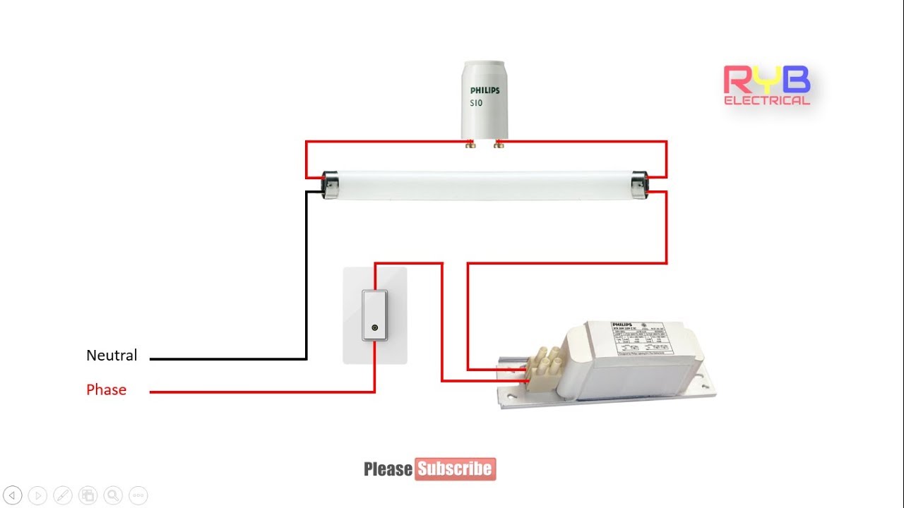
Electrical tube light connection circuit diagram. Collection of john deere wiring diagram download. So the neutral wire is continued from port 2 to pin 1 of terminal 2. This diagram illustrates wiring for one switch to control 2 or more lights. From the junction box the neutral wire is not taken out to the switch board rather it is taken out from the junction box and carried out to the port 2 of the tube light as per figure above.
The source is at sw1 and 2 wire cable runs from there to the fixtures. The hot and neutral terminals on each fixture are spliced with a pigtail to the circuit wires which then continue on to the next light. Simply light circuit analytical diagram. A wiring diagram is a streamlined standard pictorial depiction of an electric circuit.
It shows the elements of the circuit as simplified shapes and also the power as well as signal links in between the gadgets. A diagram that uses lines to represent the wires and symbols to represent components. How to install a single tube light with electromagnetic ballast. A wire already connects port 2 and pin 1 of the terminal 2.
So before we get stuck in to some wiring diagrams. Now you know how to wire a basic lighting circuit with one light switched at one point. Assortment of t8 led tube light wiring diagram. When we connect the ac supply voltage to the circuit then the starter act like short circuited and current flow through those filament located at the first and second end of the tube light and the filament generate heat and it ionized the gas mercury vapor in the fluorescent tube lamp.
Electrician circuit drawings and wiring diagrams youth explore trades skills 3 pictorial diagram. Once tested and connected to the live supply the lighting circuit will be operational. It shows the parts of the circuit as streamlined forms and also the power and signal connections between the gadgets. It s likely though you ve already read the wikipedia page about series and parallel circuits here maybe a few other google search results on the subject and are still unclear or wanting more specific information as it pertains to leds.
All the light wiring diagrams are available in the old and the new cable colours to avoid confusion. In effect this is exactly the same wiring as the diagram on the top of the page but with the utilisation of the flat twin earth cable. A wiring diagram is a simplified standard pictorial representation of an electrical circuit. A diagram that represents the elements of a system using abstract graphic drawings or realistic pictures.
We have and extensive collection of common lighting arrangements with detailed lighting circuit diagrams light wiring diagrams and a breakdown of all the components used in lighting circuits. Hopefully those looking for practical information on electrical circuits and wiring led components found this guide first. This kind of connection is used in almost all interior electrical installations.

Twin Fluorescent Lamp Wiring Diagram Pdf Download

Fluorescent Light Fixture 2 Lamp Wiring Diagram Fluorescent Light Fixture Fluorescent Light Light Fixtures

Led Tube Light Wiring Diagram Led Fluorescent Led Fluorescent Light Led Tube Light
Fuse Tube Light Circuit Diagram Tube Light Electrical Projects Circuit

Led Fluorescent Tube Wiring Diagram Bookingritzcarlton Info Led Fluorescent Tube Led Fluorescent Fluorescent Tube

New Circuit For Electronic Choke For Tubelight Diagram Tubelight Wire

Led Tube Wiring Diagram Http Bookingritzcarlton Info Led Tube Wiring Diagram Led Tubes T8 Led Tube T8 Led

Osram Led Tube Wiring Diagram Http Bookingritzcarlton Info Osram Led Tube Wiring Diagram Led Tubes T8 Led Tube T8 Led

Pin On Eletricidade

T5 Led Tube Wiring Diagram Bookingritzcarlton Info Led Tubes Led Fluorescent Tube Fluorescent Tube

Wiring Diagram Florescent Light Fluorescent Light Diagram Light

Pin On Tips References

Tube Wiring Diagram Http Bookingritzcarlton Info Tube Wiring Diagram Led Tubes T8 Led Tube Led Fluorescent Tube


