Electrical Component Diagram Symbols
Circuit Schematic Symbols Electrical Schematic Symbols Electrical Symbols Circuit Diagram

Schematic Symbols
Schematic Symbols Electrical Symbols Electronic Schematics Symbols

Electrical Wiring Diagram Symbols Bestharleylinksfo Electronics Components Symbols Electronics

Electrical Schematic Symbols Electrical Schematic Symbols Electrical Circuit Diagram Electrical Wiring Diagram

Circuit Symbols Electrical Symbols Symbols Electronics Components
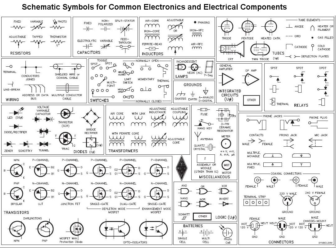
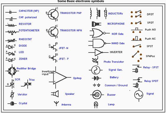
There are some standard symbols to represent the components in a circuits.
Electrical component diagram symbols. Electrical wiring comprises slight leading wires that permit electrons to go from one electronic components list and symbols towards the next and complete the circuit. Here s a printable electrical symbols chart for your reference when preparing circuit diagrams. Efficiently create modify and document electrical controls systems with autocad electrical toolset. This article shows many of the frequently used electrical symbols for drawing electrical diagrams.
Though these standard symbols are simplified the function descriptions can make you understand clearly. This article gives some of the frequently used symbols for drawing the circuits. Symbols even more the electronic components have terminals and each will have its own name and polarities. Circuit diagrams provide the component layout in any circuit.
Electrical symbols electronic symbols. An electronic symbol is a pictogram used to represent various electrical and electronic devices or functions such as wires batteries resistors and transistors in a schematic diagram of an electrical or electronic circuit these symbols are largely standardized internationally today but may vary from country to country or engineering discipline based on traditional conventions. Let s take a look at how to use the basic electrical symbols to draw a schematic diagram of the circuit and its components. The schematic diagram of an electrical circuit shows the complete electrical connections between components using their symbols and lines.
The basic is passive and. The symbols are very important to represent electronic components in a circuit diagram without electronic symbol the design of circuit and schematics are very difficult and also knowing the components is very must to read the circuit diagram representation. Electrical symbols or electronic circuits are virtually represented by circuit diagrams. Ground or earth image to be added soon.
There are many electrical and electronic schematic symbols are used to signify basic electronic or. Create panel layouts schematic diagrams and other electrical drawings. There are three d cells placed in a battery pack to power a circuit containing three light bulbs. Unlike wiring diagram it does not specify the real location of the components the line between the components does not represent real distance between them.
The symbols represent electrical and electronic components. In order to represent the various components used in the diagram electrical symbols are used. Electrical symbols virtually represent the components of electrical and electronic circuits. Electrical schematic symbol libraries select from a rich library of electrical symbols.
The resistor symbol. Use circuit builder for simple electrical design. Some most commonly used basic electrical symbols in schematic diagrams are shown below. There are many electrical symbols and their uses.

Schematic Symbols Chart Wiring Diagram Database Wiring Drafting Symbols Electrical Schematic Symbols W Electrical Schematic Symbols Electronics Circuit Circuit

Electronics Symbols Components And Circuit Diagram Reading In Hindi Urdu Youtube Electrical Symbols Symbols Electronics Components

Electrical Wiring Diagrams Symbols Chart Diagram Electrical Wiring Diagram Electrical Diagram Diagram

Electric Circuit Symbols Jpg 1297 1953 Electronic Schematics Electric Circuit Electrical Symbols

12 Volt Relay Wiring Diagram Symbols Wiringdiagram Org Diagram Toyota

More Electrical Symbols Electrical Schematic Symbols Circuit Electronic Schematics

Electrical Symbols Or Electronic Circuits Are Virtually Represented By Circuit Diagrams There Are Some Stan Electrical Symbols Electronics Circuit Electricity

Pin By Jon On Symbols Electronics Components Electrical Circuit Diagram Electrical Symbols

Standardized Wiring Diagram And Schematic Symbols April 1955 Popular Electronics Electrical Symbols Electrical Wiring Home Electrical Wiring

Schematic Symbols Chart Symbols Chart 1 3 Electrical Symbols Electrical Circuit Diagram Electrical Diagram

Electrical Symbols 16 Electrical Symbols Electrical Engineering Projects Electrical Circuit Symbols

Electronic Component Schematic Symbols Input Jacks Power Supplies And Antennas Electronic Schematics Electronics Components Diy Electronics

Electrical Wiring Diagram Legend Http Bookingritzcarlton Info Electrical Wiring Diagram Lege Electrical Wiring Diagram Electrical Symbols Electrical Diagram


