Aux Relay Circuit Symbol

12v Relay Wiring Diagram 5 Pin Bokeh Aplikasi
Devices Symbols And Circuits Electrical Circuits Electric Equipment

Wiring Auxiliary Lights Automotive Repair Automotive Electrical Mechanical Engineering Projects

Aux Light Wiring Diagram 5 Wire Relay Electrical Wiring Diagram Trailer Light Wiring Automotive Electrical

Basic Of Relay Definition Configuration And Symbols Electrical Blog

12v Relay Circuit Tags Wiring Diagram Car Amp In 12 Volt Carlplant For Relays 1015x1024 In 12 Vo Motorcycle Wiring Car Audio Installation Automotive Electrical

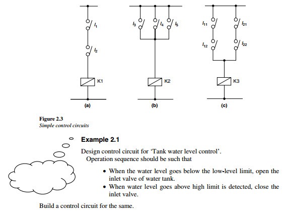
Electrical symbols control circuits can be represented pictorially in various ways.
Aux relay circuit symbol. Relay logic circuit examples and working. Electrical schematics are commonly classified into power circuit and control circuit. Most of the time a small voltage or current is used to switch other voltages or higher currents that may be electromechanical or fully electronic type. A power circuit consists of the main power device a motor a generator or other power devices along with heavy power conductors contactors.
They indicate the machine operation. One of the more common approaches is to use control logic diagrams which use common symbols to represent control components. The circuit symbols for electromechanical relays can vary somewhat like most circuit symbols. Circuit symbol of a relay note that on this symbol both normally open and normally closed contacts are shown.
Although control symbols vary throughout the world the symbols used in this course are common in the united states and many other countries. The relay coil symbol is used to indicate control relay or motor starter and sometimes even contactor or timer. Auxiliary relay block symbol static relay with terminals for external auxiliary voltage supply u relay with make contact delayed when the relay is energized. The given symbol denotes pilot lamp or simply a bulb.
Electrical circuits electrical circuits are circuits used to interconnect different electrical equipments together to enable the working of an electrical device. A relay is an electrically operated switch it consists of a set of input terminals for a single or multiple control signals and a set of operating contact terminals the switch may have any number of contacts in multiple contact forms such as make contacts break contacts or combinations thereof. Relay symbols and electromagnets. The relay are switching devices activated by signals.
Relay symbol measurement relays low power or sync relay it is used to open or close an auxiliary or secondary circuit depending on whether the intensity or power of the circuit being controlled remains in the range of a predetermined value and does not fall below that value they are known as synchrony relays since guarantee that there is. Relays are used where it is necessary to control a circuit by an independent low power signal. The control terminals is operated by a single or multiple control signals to swtich the contact terminals. They are used for switching relatively high power circuits using low power signals.
The most widely used format shows the relay coil as a box and the contacts are placed close by as shown below. In the design of electrical power systems the ansi standard device numbers ansi ieee standard c37 2 standard for electrical power system device function numbers acronyms and contact designations identifies the features of a protective device such as a relay or circuit breaker these types of devices protect electrical systems and components from damage when an unwanted event occurs such.

Electric Fans With Relay Wiring Electricity Automotive Mechanic Electric Fan
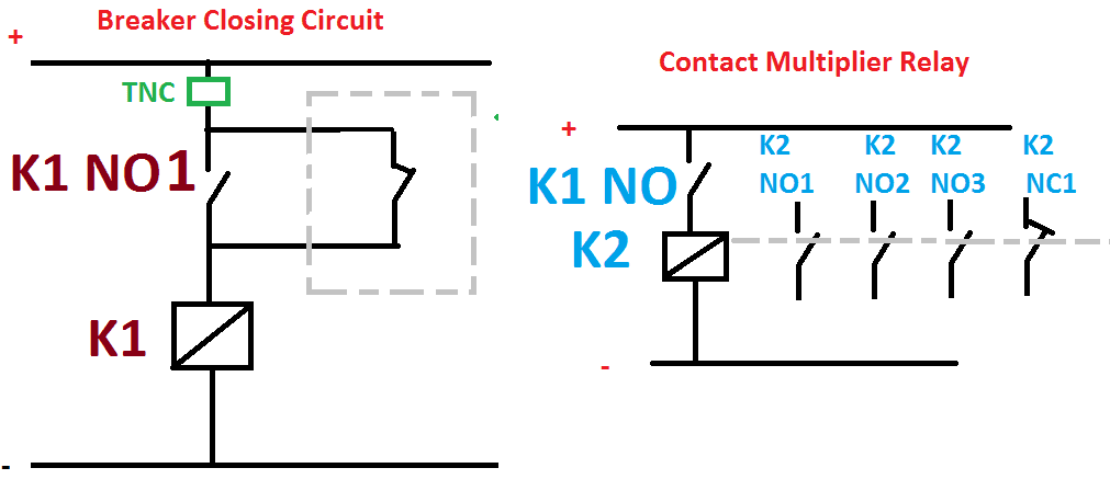
Contact Multiplier Relay Working Function Wiring Diagram Electrical4u

Best Relay Wiring Diagram 5 Pin Bosch Endearing Enchanting Blurts Me With Images Electrical Circuit Diagram Circuit Diagram Relay

Wiring Auxiliary Lights Boat Wiring Car Mechanic Trailer Light Wiring

Bosch 5 Pin Relay Wiring Diagram To Electrical Diagram Circuit Diagram Automotive Electrical
Overload Relays Contactors Overloads Product Guides

Pin By Gsa Scott On Fabrication Relay Car Audio Installation Repair

Best 12v Relay Wiring Diagram Pin At Switch 5 How To Wire A Mekanik Mobil Teknik Mesin Teknik Listrik

Simple Relaycircuit Is An Electrically Operated Switch Many Relays Use An Electromagnet To Mechanic Automotive Electrical Electricity Basic Electrical Wiring

12v 5 Pin Relay Wiring Diagram Deltagenerali Me Light Switch Wiring Electrical Wiring Diagram Electrical Circuit Diagram

Wiring Diagram Incredibleiring For Relay Photo New Bosch Horn Electrical Wiring Diagram Electrical Circuit Diagram Diagram

Defender 90 2 8i Spotlights Motorcycle Wiring Car Audio Installation Automotive Electrical

Electrical Relay And Solid State Relays For Switching


